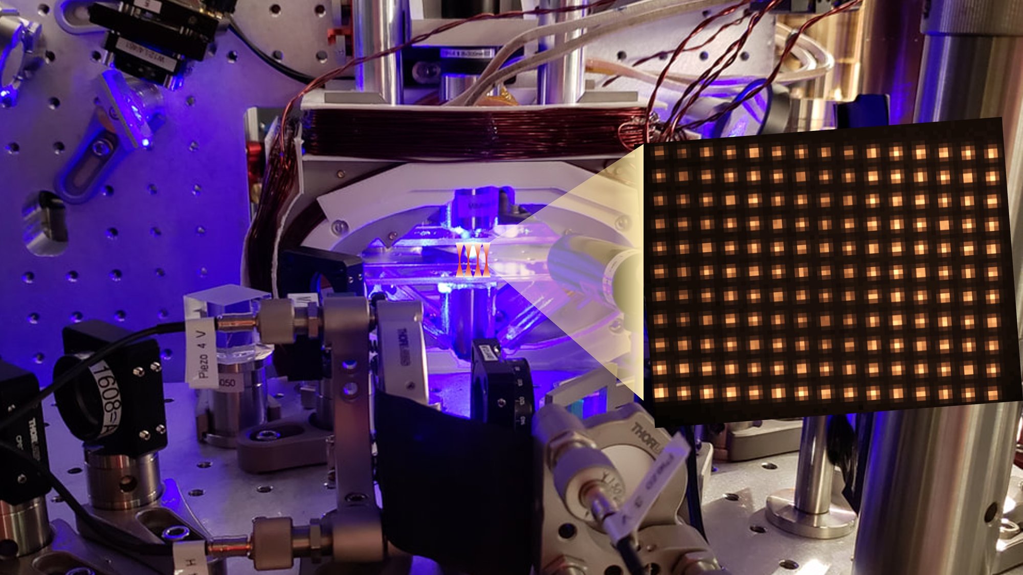
Iterative assembly of 171Yb atom arrays in cavity-enhanced optical lattices
As Seen In: Arxiv
Atom Computing
Abstract
Assembling and maintaining large arrays of individually addressable atoms is a key requirement for continued scaling of neutral-atom-based quantum computers and simulators. In this work, we demonstrate a new paradigm for assembly of atomic arrays, based on a synergistic combination of optical tweezers and cavity-enhanced optical lattices, and the incremental filling of a target array from a repetitively filled reservoir. In this protocol, the tweezers provide microscopic rearrangement of atoms, while the cavity-enhanced lattices enable the creation of large numbers of deep optical potentials that allow for rapid low-loss imaging of atoms. We apply this protocol to demonstrate deterministic filling (99% per-site occupancy) of 1225-site arrays. Because the reservoir is repeatedly filled with fresh atoms, the array can be maintained in a filled state indefinitely. We anticipate that this protocol will be compatible with mid-circuit reloading, which will be a key capability for running large-scale error-corrected quantum computations whose durations exceed the lifetime of a single atom in the system.
I. Introduction
Individually controlled neutral atoms provide a promising platform for quantum information processing and simulation, and expanding the size and control of these systems represent key challenges in the ongoing push to access regimes beyond the capabilities of classical simulation. Tweezer arrays and optical lattices have emerged as core technologies for optically trapping and manipulating cold atoms, each with complementary capabilities. Optical lattices provide a well-defined potential landscape with features on the sub-wavelength scale, which can enable tight confinement for imaging and a clean optical potential for simulations involving itinerant atoms [1]. Optical tweezers provide a means of selectively manipulating individual atoms [2]. Notably, tweezer arrays have gained prominence for deterministic assembly of atomic arrays [3, 4, 5] with up to hundreds of atoms [6, 7] and inter-atomic spacing suitable for enabling interactions between atoms through excitation to Rydberg states [8, 9, 10, 6, 7, 11, 12]. Recently, optical tweezers and lattices have been combined to create programmable initial conditions in a Hubbard-regime system [13, 14], and to enable enhanced scaling of atom number for metrology [15] and quantum simulation[16].
The merits of optical lattices can be further enhanced through the use of optical buildup cavities. Optical cavities enhance the lattice depth by enabling the constructive interference of many overlapped reflections of laser light, in turn enabling the creation of arrays of many deep traps [17, 18].
In this work, we combine the capabilities of tweezers and cavity-enhanced optical lattices to demonstrate an iterative approach to creating large arrays of individually-controlled atoms. Typically, tweezer rearrangement is performed by stochastically loading up to a single atom into each trap within an array [19], imaging the atoms to determine trap occupancy, and then rearranging atoms within the array to create a deterministically occupied sub-array [4, 5]. Crucially, the number of atoms contained in the final array with this approach is no greater than the number initially loaded. Further, because the initial loading is stochastic, the number of sites in the array must generally be substantially larger than desired final sub-array (though under certain conditions, near-deterministic loading can be achieved [20, 21], and several initial arrays can be used to increase the number of available atoms [22]). Recently, repeated loading of a “buffer” array from an optical dipole trap “reservoir” has demonstrated that one can decouple the filling of a six-site target array from a single loading of a cold reservoir [23]. In this work, we extend this concept to repeated loading of a reservoir array, from which we create a deterministically filled target array (typically 99% occupancy) of over 1200 171Yb atoms in 1225 sites. This is made possible by combining optical tweezer arrays with a cavity-enhanced optical lattice to provide both microscopic control and the large number of deep traps required for rapid, high-fidelity, low-loss imaging of large numbers of atoms.
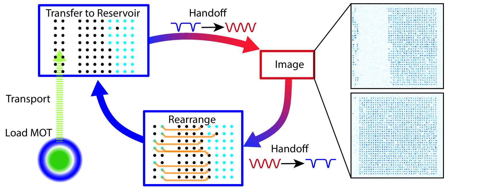
A single cycle of loading proceeds as follows (See figure 1): Atoms are collected and cooled in a magneto-optical trap 30 cm below a “science region” where we create a cavity-enhanced optical lattice, as well as tweezer arrays projected through a high-numerical-aperture imaging. The atoms are then transported into the science region, where they are loaded into a set of tweezers that form the reservoir. The reservoir sits adjacent to the target tweezer array, which on all loading cycles but the first is already partially occupied with atoms loaded on previous cycles. The atoms from both reservoir and target tweezer arrays are then transferred into the trapping potential of the cavity-enhanced optical lattice, where we perform site-resolved nondestructive fluorescence imaging to determine which sites of each tweezer array were occupied. We then transfer the atoms back from the cavity lattice to the tweezers, and use a single separate “rearrangement” tweezer to move atoms from the reservoir into empty target tweezers. This defines one loading cycle. Over the course of multiple cycles, the number of atoms in the target array increases until the target array is filled. At this point, further operations may be performed on the atoms, and subsequent loading cycles are applied to maintain a filled array.
Because we reload the reservoir on each loading cycle from a fresh magneto-optical trap, we can continue loading the target array indefinitely. In the near-term, this allows for relatively high data-rates for quantum simulation and computation with large system sizes, and could also be of benefit for optical clocks for high statistical precision with low dead-time [24]. Ultimately, the ability to reload new atoms while maintaining both the presence and coherence of existing atoms will be a key capability for performing error-corrected quantum computations, where execution of an algorithm may take much longer than the lifetime of any given atom in the system. When combined with site-selective hiding [25, 26] and mid-circuit rearrangement techniques already demonstrated in a similar system [26], we anticipate that this protocol will be compatible with mid-circuit reloading of atoms into the array. As a means of maintaining a fully filled array, our approach represents an alternative to the interleaved use of two atomic species [27, 28]. Unlike the two-species approach, the method presented here does not require simultaneous replacement of the entire array, and so may be expected to ease requirements for scaling to large arrays, and would not require inter-species gates [29] in order to replenish the array during a quantum computation.
II. Trapping and imaging atoms in a 3D cavity enhanced lattice
Rapid low-loss imaging of the locations of atoms is essential to our repeated loading protocol. Because atoms are heated by the photon scattering required for imaging, deep optical traps and imaging protocols with low equilibrium temperatures are required to prevent atom loss. Optical tweezers represent a common method for achieving deep optical traps – the tight foci can provide high intensities for moderate powers. However, the total power requirement for a large array of tweezers presents scaling limitations due to limited available laser power. Cavity-enhanced optical lattices offer an alternative path to achieving many deep traps. While the laser intensity in a lattice is spread over a larger cross-sectional area than in optical tweezers both because it spans the regions between utilized sites, and because the Gaussian mode profile must be large compared to the size of the array to achieve uniform trapping, interference of many reflected paths in a cavity-supported lattice can enable more power-efficient generation of traps.
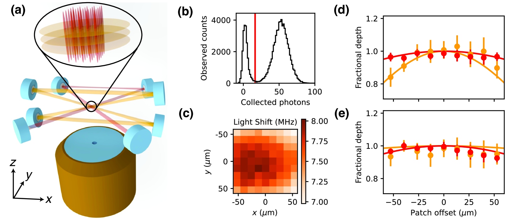
We employ two intersecting optical cavities to provide tight confinement in three dimensions, as shown in figure 2a. The first cavity – which we call the XY cavity – is a retro-reflected four-mirror cavity whose mode intersects itself at the location of the atoms. The polarization is perpendicular to the plane of propagation, providing interference between the two crossed portions of the cavity mode [30]. Compared to using two crossed non-interfering lattices [31, 18], and assuming equal cavity finesse, this configuration provides an eight-fold enhancement in trap depth (defined as the potential barrier between adjacent lattice sites) per unit of total laser power. The XY cavity provides tight confinement in the directions perpendicular to the high numerical aperture optical axis used for the tweezers and imaging. The second cavity, which we call the Z cavity, is a four-mirror running wave cavity whose mode intersects itself at the location of the atoms [32] at 15 degree angles from the XY plane. This provides confinement along the tweezer axis. The polarization of the Z cavity is also oriented perpendicular to its intersection plane, enabling complete interference of the crossing modes. Each cavity has two highly reflecting mirrors, and two matched partially transmitting mirrors. The finesse of the XY and Z cavities are 2900(100) and 3000(100) respectively, and the design mode waists at the location of the atoms are 268 𝜇m and 183 𝜇m respectively. For imaging, we typically operate with XY (Z) trap frequencies near 160 kHz (50 kHz), corresponding to 330 𝜇K (260 𝜇K) deep traps.
We image atoms using the the narrow-linewidth (180 kHz) 1S0 to 3P1 transition, which simultaneously provides cooling and scattering of photons for detection [33, 34, 26]. We use a single beam, detuned several hundred kHz from the 𝐹=3/2, 𝑚𝑓=3/2 state, with projection onto both the X and Z directions. For applications like array assembly where we wish to determine the presence of an atom but not the state of its nuclear spin (the qubit we use for quantum information applications), we simultaneously apply optical pumping on the 1S0 𝑚𝑓=−1/2 to 3P1 𝐹=1/2, 𝑚𝑓=1/2 transition with light incident along the magnetic field (𝑥 direction). At our benchmark imaging parameters, we collect 50 photons in 7 ms, and distinguish occupied from unoccupied sites with a fidelity of approximately 99.95%, as determined from the overlap error in a double-Gaussian fit to the bimodal distribution of counts. Atom loss during such an image is 2(1)×10−3. Spin-selective imaging requires us to omit the optical pumping, and rely on the combination of frequency and polarization selectivity within the 3P1 manifold to create a large imbalance of scattering between the two nuclear spin states, as demonstrated in optical tweezers in refs. [34, 26]. The omission of the optical pumping does not modify the photon scattering rate appreciably, but does introduce a finite spin flip probability of of 4(1)×10−3 for our typical imaging parameters, measured as an additional apparent loss in repeated images of 1S0 𝑚𝑓=1/2. These spin flips are likely due to the fact that the lattice polarization is perpendicular to the magnetic field, and so can induce spin-changing transitions within the 3P1 manifold [34].
In order to ensure uniform detuning of the imaging transition across the array and between different motional states, we operate with a trapping wavelength that has equal polarizability for the ground and excited states of the imaging transition – a so-called magic wavelength. For the 1S0 𝑚𝑓=1/2 to 3P1 𝑚𝑓=3/2 transition, we find a magic condition near 783.8 nm.
We characterize the homogeneity of the optical lattice potential by probing the 1S0 𝑚𝑓=1/2 to 3P1 𝐹=3/2, 𝑚𝑓=−1/2 transition, for which the excited state has approximately 40% higher polarizability than the ground state. We infer the trap depth from the transition light shifts, measured using optical pumping from the 1S0 𝑚𝑓=1/2 state, followed by spin-selective imaging (fig. 2c). By varying the power in each cavity, we can extract their independent contributions, displayed averaged over rows and columns in figure 2d,e. Over our 115 𝜇m square array, peak deviations are within 20% for the Z lattice and 10% for the XY lattice. Because we operate with a magic wavelength condition for critical operations, these deviations do not present a major limitation.
III. Repeated loading to build up a large array
In this section, we describe our continuous loading protocol in detail, and characterize its performance for loading large arrays.
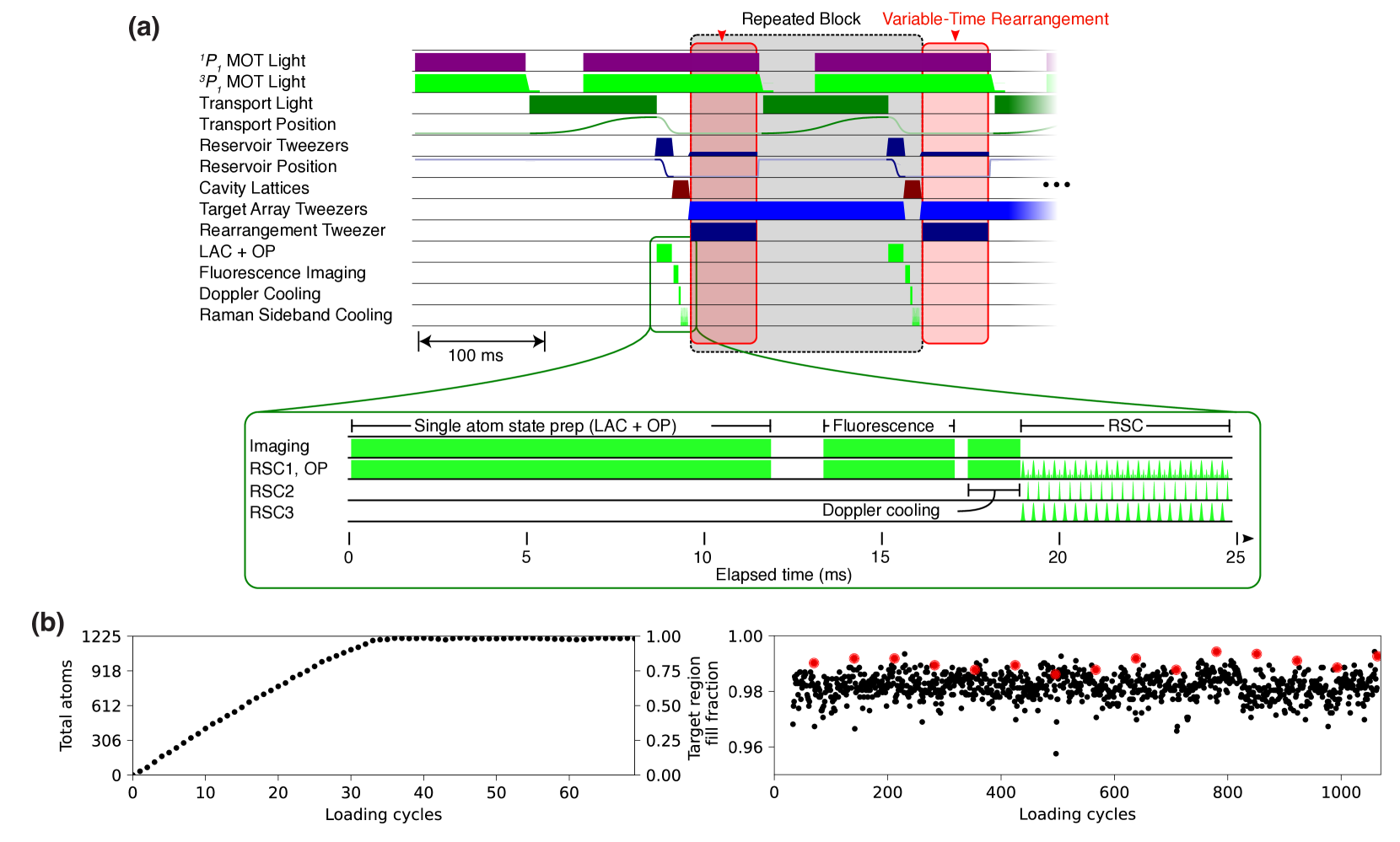
Our loading cycle (illustrated in figure 3a) begins with collecting atoms from a pre-cooled atomic beam into a magneto-optical trap (MOT) using a “core-shell” configuration [35]. In this MOT, each beam consists of a ring of 399 nm light near resonance with the broad linewidth 1S0 to 1P1 transition surrounding a central region with only 556 nm light near resonance with the narrow linewidth 1S0 to 3P1 transition. The shell is primarily responsible for capturing atoms from the incident beam, while the low Doppler temperature of the narrow transition used in the core enables cooling to several 10 𝜇K. Because atoms do not scatter light from the broad transition except during initial capture, the core-shell design poses less risk of generating scattered photons that may be absorbed by atoms in the target array – the total scattering rate on the narrow transition is much lower, and the large magnetic field present in the science region dramatically suppresses reabsorption of photons via the narrow-line transition. In our operating condition, the 399 nm photon scattering rate is about 2 orders of magnitude lower than the broad-line stage of a sequential MOT. We find that the core-shell MOT configuration increases the MOT loading rate by roughly a factor of two, compared to a more standard sequential MOT configuration in a static magnetic field.
From the core-shell MOT, atoms are loaded into a vertically oriented standing-wave lattice formed by counterpropagating 532 nm laser beams focused at the location of the atoms. Loading is achieved by overlapping the lattice with the center of the MOT, followed by reducing the detuning and intensity of the 556 nm light. We then extinguish the MOT light and transport the atoms vertically by synchronously applying a frequency offset to the upward-going and downward-going lattice beams, and translating their foci [26]. This brings the atoms 30 cm vertically into the vicinity of the target array, at which point we transfer the atoms into a reservoir array formed by 483 nm tweezers (another magic wavelength for the 1S0 to 3P1 transition [26]). To avoid disturbing atoms already loaded into the target array, this transfer takes place at a location displaced 170 𝜇m horizontally from the target array. No dissipation is required to transfer atoms from the transport lattice to the tweezers – loading is achieved by simply increasing the intensity of the tweezers while the lattice is overlapped and then decreasing the intensity of the lattice. Once loaded, the reservoir array is translated to be directly adjacent to the target array by changing the angle of a galvo mirror that is imaged onto the entrance pupil of the objective.
The target array consists of a rectangular array of tweezer spots formed with light at 459.5960(5) nm wavelength, a magic wavelength for the 1S0 to 3P0 clock transition [26, 36], and a set of tweezer spots formed by light at 423.31 nm, which is near resonance with a transition between 3P1 to a higher-lying 6S8S 3S1 state. Both wavelengths provide large light-shifts to atoms in 3P1, which prevents unwanted scattering from atoms loaded in these tweezer arrays, and can be used interchangeably for this work. For this work, we operate with a 35x35-site target array with 3.3 𝜇m spacing, comprised of two separate rectangular arrays each using one of the two previously mentioned wavelengths. We have also operated with overlapped full-size arrays to achieve sufficient trap depth, and obtained similar results. However, the overlapped condition is more sensitive to alignments, and so we use spatially separated arrays for all results presented here.
While translating the reservoir array adjacent to the target array, both arrays are illuminated with light resonant with the 1S0 to 3P1 𝐹=3/2, 𝑚𝑓=3/2 transition. This induces light-assisted collisions between atoms in the reservoir tweezers, resulting in either zero or one atom in each reservoir tweezer with approximately equal probability [19]. Importantly, the tweezer light illuminating the atoms in the target array prevents them from scattering the light used to induce collisions, which might otherwise cause loss of existing atoms in the target array. Next, atoms from both tweezer arrays are transferred into the optical lattice and imaged, as described above. The imaging leaves the atoms at a temperature of 20 𝜇K, which is too warm to efficiently transfer into the relatively shallow tweezers of the target array. Following each image, we apply Doppler and Raman sideband cooling to reach an average of ∼ 0.1 motional quanta in each direction (Appendix A). Once cooled, the atoms are transferred back into the tweezer arrays, and a single optical tweezer derived from the same laser as the reservoir light is used to transfer atoms from filled sites of the reservoir array into empty sites of the target array. This completes a single loading cycle.
In order to shorten the time required to build up an atomic array, and to limit the losses associated with background gas collisions, we load the MOT at the same time as performing operations in the science chamber. This is made possible by the spatial separation between MOT and science regions, and by the fact that we operate with static magnetic fields: we can simultaneously operate with the magnetic field gradients required by the MOT and the large 500 Gauss homogeneous bias field that is desirable for imaging and other operations required in the science regions. The low scattering rate of 399 nm photons, combined with the large magnetic field and spatial separation between the MOT and science regions prevents light scattered in the MOT from being reabsorbed by atoms in the science region, which could cause heating or decoherence.
Figure 3b shows examples of the atom number increasing as a function of load cycles, with 105 sites in the reservoir and 1225 sites in the target array. At first, the atom number increases approximately linearly as roughly 45 atoms are transferred into the target array per cycle. The loading rate decreases slightly as the array fills, as some atoms from the reservoir are used to counteract loss. Once the number of vacancies in the target array drops below the typical number of atoms in the reservoir, an equilibrium is reached with the vacancy fraction set by the per cycle probability of atom loss.
In figure 3b, the atom number is inferred from the image taken before rearrangement, so the measured fill fraction is sensitive to all losses that occur between such images. This fill fraction is typically 98%, with the largest single loss contribution coming from vacuum loss during the typical 300 ms time between images due to our approximately 30 s vacuum lifetime. We can add additional diagnostic images directly after rearrangement to determine the atom number available for computation, and observe typical filling fractions of 99%, again dominated by vacuum loss during the 150 ms typically allocated for rearrangement. Our experimental control allocates a variable duration for rearrangement that depends on the number and length of moves to be performed, as well as the time required to compute the moves. The durations above are typical for the 1225-site arrays studied in this work. Other sources of loss or potential loss are described in more detail in Appendix B, and include the handoff between the tweezer arrays and the lattice, and imaging loss and infidelity.
IV. Conclusions and outlooks
We have demonstrated an iterative method for assembling large arrays of individually controlled neutral atoms, suitable for quantum computation, simulation, and metrology. Through this approach, we decouple the final size of the array from the number of atoms that can be loaded at once, and the need to create many tweezer traps with sufficient depth for loading and imaging atoms. In particular, our reservoir and lattice traps are much deeper than the target tweezer traps, allowing for the use of large numbers of sites with moderate laser power. Our current arrays have percent-level defects, which could be straightforwardly reduced with improved vacuum.
For quantum computing applications, our iterative loading may be combined with recently demonstrated mid-circuit measurement techniques [25, 26] in order to achieve continuous mid-circuit refilling of array defects. This capability will be critical for mitigating the effect of atom loss during execution of complex error-corrected circuits that may extend beyond the lifetime of an individual atom in the array.
V. Appendix A: Raman Sideband Cooling
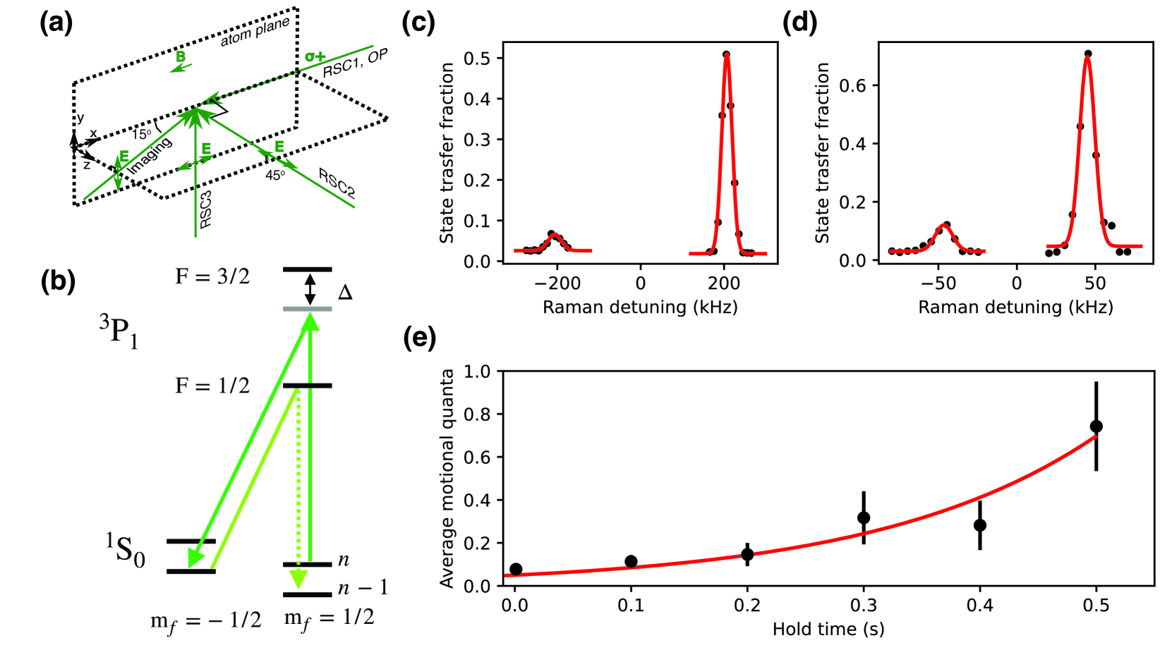
Transferring atoms from the lattice into shallow tweezer traps with low loss requires that the atoms be much colder than the depth of the tweezer traps. By operating with colder atoms, we can use shallower tweezers, and in turn scale to larger array sizes. To accomplish this, we use Raman sideband cooling (RSC) between the two ground nuclear spin states [21, 25]. For the motional Raman transitions, we use two pairs of beams oriented along the 𝑥 and 𝑦 directions, and along the 𝑥 and 𝑧 directions to provide cooling along all three directions (fig. 4a). The Raman transitions transfer atoms from 1S0 𝑚𝑓=1/2 to 1S0 𝑚𝑓=−1/2, state, and are detuned from the motional carrier transition by the appropriate trap oscillation frequency in order to reduce the motional state by one quanta (fig. 4b). Optical pumping is provided by a beam oriented along 𝑥 and the magnetic field that addresses the 1S0 𝑚𝑓=−1/2 to 1P1 𝐹=1/2, 𝑚𝑓=1/2 transition.
We perform 20 iterations of cooling, with each iteration consisting of a 𝜋 pulse on the red motional sideband for each pair, followed by optical pumping. The pulse durations are 200 𝜇s for the 𝑥𝑦 pair and 100 𝜇s for the 𝑥𝑧 pair (tuned to the 𝑧 direction sidband), and 50 𝜇s for optical pumping. The total cooling sequence lasts 8 ms. In typical sequences, we apply a 2 ms Doppler cooling pulse prior to the RSC sequence using the same beam as for the imaging pulse, but with lower intensity and farther red-detuning. The Doppler cooling results in 10 𝜇K temperature in the cavity as measured by a release and recapture protocol [37]. This roughly corresponds to 1 motional quanta occupancy in the cavity. Subsequent RSC reduces the average motional quanta to in each direction to ∼ 0.1, as evident from the sideband imbalance following cooling (fig. 4c, d).
We measure heating in the 𝑥, 𝑦 plane while holding atoms in the lattice by performing Raman sideband spectroscopy to extract the average motional quantum number 𝑛¯𝑥𝑦 as a function of time. We fit this quantity to a function representing exponential growth, as expected for parametric heating due to intensity fluctuations of the lattice [38], and extract an exponential time-constant of 190(40) ms. This is likely due to conversion of laser frequency noise to amplitude by the cavity resonance, and could be improved by optimizing the lock of lasers to the cavity.
VI. Appendix B: Sources of Per-Cycle Loss
Vacuum loss due to the finite duration of loading cycles is the single largest source of loss in our system, contributing percent-level per-cycle loss. Because our loading cycle is of variable length, and because the vacuum level in our system can fluctuate from day to day, it is difficult to estimate its exact contribution. However, typical values for the loading cycle duration and vacuum lifetime are 300 ms and 30 s respectively, so 1% represents a typical value for this loss. In this section, we describe other loss sources that contribute to a lesser degree, especially if parameters are not carefully optimized. In general, the loss mechanisms described below both limit the size of array we can ultimately load (as the reservoir must be large enough to replace lost atoms), and limit the final fill fraction of the array.
As described in the main text, typical imaging loss is 2(1)×10−3 where roughly 30 % is the vacuum loss and the rest is the Raman scattering out of 3P1 due to the trap light , and the discrimination infidelity is typically at or below the 10−3 level. If an atom within the target array is lost during the image after scattering enough photons to be identified as present, the defect will not be filled during the subsequent rearrangement step, leading to a defect in the array. If a site within the array is incorrectly identified as empty, an atom will likely be added to that site from the reservoir, and subsequently undergo lossy collisions with the original occupant. Empty sites within the target or reservoir arrays that are mistakenly identified as full will lead to a previous defect not being repaired. However, because defects are rare, this mechanism is less problematic. We currently operate with a discrimination threshold that balances the correct identification of empty and full sites. In a system where imaging losses and infidelity become dominant loss sources (a system with better vacuum), it may be advantageous to bias the threshold to minimize the more problematic forms of imaging error.
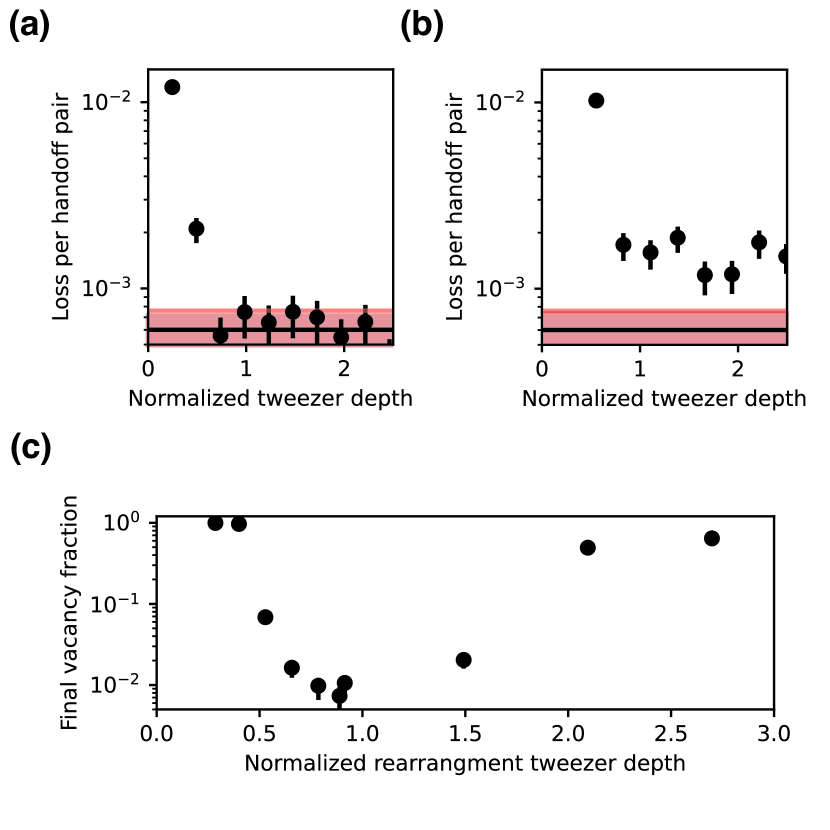
Each image requires handing off atoms from the tweezer arrays into the lattice and back. We find that this process is sensitive to the alignment of the two arrays on the scale of a single lattice site, to the depth of the tweezer arrays, and to the temperature of the atoms. Atom temperature and alignment are described in Appendix A and C, respectively. We isolate the effect of trap depth on handoff for cold atoms and well-aligned arrays by performing 25 subsequent handoff pairs between tweezers and lattice in figure 5a, b. We perform our usual Raman sideband cooling (RSC) each time the atoms are in the lattice between handoffs. For 459 nm tweezer depths below 75% of our typical operating conditions, we observe significant loss. Above this power level, we observe a constant loss rate of 0.0006(1), which is consistent with data taken with the handoff omitted, and with our typical vacuum losses. The 423 nm tweezers show a similar behavior, though with a slightly higher loss rate of 0.0015(2) at high powers, likely due to worse alignment or optical aberrations. If the tweezers are aligned to the trough of the XY cavity intensity, the loss can be as high as 0.02.
In principle, moving new atoms in the target array may cause loss of existing atoms in the array, as the rearrangement tweezer moves near the occupied target sites. We assess this possibility in figure 5c by measuring the final fill fraction versus the depth of the rearrangement tweezer. For a rearrangement tweezer that is too shallow, we observe a lower loading rate and so a lower final fill fraction. For too deep a tweezer, we also see a reduction in the final fill fraction, as the rearrangement leads to loss of existing atoms. Near our typical operating conditions, we observe a region with weak dependency of the fill fraction on the tweezer power.
VII. Appendix C: Alignment of arrays
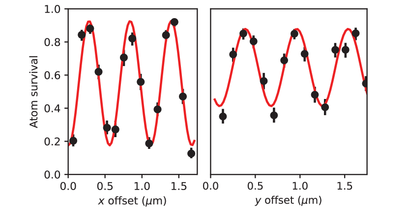
Precise alignment of the different optical potentials is critical for the performance of our repeated loading protocol. The alignment of the target tweezer arrays to the optical lattice is particularly sensitive, as misalignment here can lead to increased handoff loss that can limit both the largest array that can be loaded, and the final fill fraction of the array.
Alignment of the arrays involves first matching the spacing and tilt of the lattice – quantities which do not drift appreciably over time – and then at a higher frequency aligning the 𝑥 and 𝑦 offsets. We obtain the correct spacings and tilts by populating the lattice with atoms transferred from an expanded but sparse version of the reservoir array. We image the atoms in the lattice to determine the lattice grid, and then in the reservoir tweezers to determine required corrections to the tweezer array. We then use a camera whose imaging system is corrected for chromatic shifts between the different tweezer wavelengths to register the target array tweezers to the reservoir tweezers.
We then optimize the translation alignment by performing repeated handoffs between the tweezers and the lattice and scanning the position offset of the tweezer arrays. We observe a periodic modulation in the atomic survival (fig. 6), which we fit to determine the optimal alignment. This process is repeated as necessary to ensure alignment of the arrays.
References
- Gross and Bloch [2017]↑C. Gross and I. Bloch, Quantum simulations with ultracold atoms in optical lattices, Science 357, 995 (2017).
- Kaufman and Ni [2021]↑A. M. Kaufman and K.-K. Ni, Quantum science with optical tweezer arrays of ultracold atoms and molecules, Nature Physics 17, 1324 (2021).
- Kim et al. [2016]↑H. Kim, W. Lee, H.-g. Lee, H. Jo, Y. Song, and J. Ahn, In situ single-atom array synthesis using dynamic holographic optical tweezers, Nature Communications 7, 13317 (2016).
- Barredo et al. [2016]↑D. Barredo, S. De Léséleuc, V. Lienhard, T. Lahaye, and A. Browaeys, An atom-by-atom assembler of defect-free arbitrary two-dimensional atomic arrays, Science 354, 1021 (2016).
- Endres et al. [2016]↑M. Endres, H. Bernien, A. Keesling, H. Levine, E. R. Anschuetz, A. Krajenbrink, C. Senko, V. Vuletic, M. Greiner, and M. D. Lukin, Atom-by-atom assembly of defect-free one-dimensional cold atom arrays, Science 354, 1024 (2016).
- Scholl et al. [2021]↑P. Scholl, M. Schuler, H. J. Williams, A. A. Eberharter, D. Barredo, K.-N. Schymik, V. Lienhard, L.-P. Henry, T. C. Lang, T. Lahaye, et al., Quantum simulation of 2d antiferromagnets with hundreds of Rydberg atoms, Nature 595, 233 (2021).
- Ebadi et al. [2021]↑S. Ebadi, T. T. Wang, H. Levine, A. Keesling, G. Semeghini, A. Omran, D. Bluvstein, R. Samajdar, H. Pichler, W. W. Ho, et al., Quantum phases of matter on a 256-atom programmable quantum simulator, Nature 595, 227 (2021).
- Wilk et al. [2010]↑T. Wilk, A. Gaëtan, C. Evellin, J. Wolters, Y. Miroshnychenko, P. Grangier, and A. Browaeys, Entanglement of two individual neutral atoms using Rydberg blockade, Phys. Rev. Lett. 104, 010502 (2010).
- Isenhower et al. [2010]↑L. Isenhower, E. Urban, X. L. Zhang, A. T. Gill, T. Henage, T. A. Johnson, T. G. Walker, and M. Saffman, Demonstration of a neutral atom controlled-NOT quantum gate, Phys. Rev. Lett. 104, 010503 (2010).
- Madjarov et al. [2020]↑I. S. Madjarov, J. P. Covey, A. L. Shaw, J. Choi, A. Kale, A. Cooper, H. Pichler, V. Schkolnik, J. R. Williams, and M. Endres, High-fidelity entanglement and detection of alkaline-earth Rydberg atoms, Nature Physics 16, 857 (2020).
- Schine et al. [2022]↑N. Schine, A. W. Young, W. J. Eckner, M. J. Martin, and A. M. Kaufman, Long-lived bell states in an array of optical clock qubits, Nature Physics 18, 1067 (2022).
- Bluvstein et al. [2023]↑D. Bluvstein, S. J. Evered, A. A. Geim, S. H. Li, H. Zhou, T. Manovitz, S. Ebadi, M. Cain, M. Kalinowski, D. Hangleiter, et al., Logical quantum processor based on reconfigurable atom arrays, Nature , 1 (2023).
- Young et al. [2022]↑A. W. Young, W. J. Eckner, N. Schine, A. M. Childs, and A. M. Kaufman, Tweezer-programmable 2d quantum walks in a Hubbard-regime lattice, Science 377, 885 (2022).
- Young et al. [2023]↑A. W. Young, S. Geller, W. J. Eckner, N. Schine, S. Glancy, E. Knill, and A. M. Kaufman, An atomic boson sampler, arXiv preprint arXiv:2307.06936 (2023).
- Young et al. [2020]↑A. W. Young, W. J. Eckner, W. R. Milner, D. Kedar, M. A. Norcia, E. Oelker, N. Schine, J. Ye, and A. M. Kaufman, Half-minute-scale atomic coherence and high relative stability in a tweezer clock, Nature 588, 408 (2020).
- Tao et al. [2023]↑R. Tao, M. Ammenwerth, F. Gyger, I. Bloch, and J. Zeiher, High-fidelity detection of large-scale atom arrays in an optical lattice, arXiv preprint arXiv:2309.04717 (2023).
- Bloom et al. [2014]↑B. Bloom, T. Nicholson, J. Williams, S. Campbell, M. Bishof, X. Zhang, W. Zhang, S. Bromley, and J. Ye, An optical lattice clock with accuracy and stability at the 10-18 level, Nature 506, 71 (2014).
- Park et al. [2022]↑A. J. Park, J. Trautmann, N. Šantić, V. Klüsener, A. Heinz, I. Bloch, and S. Blatt, Cavity-enhanced optical lattices for scaling neutral atom quantum technologies to higher qubit numbers, PRX Quantum 3, 030314 (2022).
- Schlosser et al. [2001]↑N. Schlosser, G. Reymond, I. Protsenko, and P. Grangier, Sub-Poissonian loading of single atoms in a microscopic dipole trap, Nature 411, 1024 (2001).
- Brown et al. [2019]↑M. O. Brown, T. Thiele, C. Kiehl, T.-W. Hsu, and C. A. Regal, Gray-molasses optical-tweezer loading: Controlling collisions for scaling atom-array assembly, Phys. Rev. X 9, 011057 (2019).
- Jenkins et al. [2022]↑A. Jenkins, J. W. Lis, A. Senoo, W. F. McGrew, and A. M. Kaufman, Ytterbium nuclear-spin qubits in an optical tweezer array, Phys. Rev. X 12, 021027 (2022).
- Pause et al. [2024]↑L. Pause, L. Sturm, M. Mittenbühler, S. Amann, T. Preuschoff, D. Schäffner, M. Schlosser, and G. Birkl, Supercharged two-dimensional tweezer array with more than 1000 atomic qubits, Optica 11, 222 (2024).
- Pause et al. [2023]↑L. Pause, T. Preuschoff, D. Schäffner, M. Schlosser, and G. Birkl, Reservoir-based deterministic loading of single-atom tweezer arrays, Physical Review Research 5, L032009 (2023).
- Dick [1989]↑G. J. Dick, Local oscillator induced instabilities in trapped ion frequency standards, in Proceedings of the 19th Annual Precise Time and Time Interval Systems and Applications Meeting (1989) pp. 133–147.
- Lis et al. [2023]↑J. W. Lis, A. Senoo, W. F. McGrew, F. Rönchen, A. Jenkins, and A. M. Kaufman, Midcircuit operations using the omg architecture in neutral atom arrays, Phys. Rev. X 13, 041035 (2023).
- Norcia et al. [2023]↑M. A. Norcia, W. B. Cairncross, K. Barnes, P. Battaglino, A. Brown, M. O. Brown, K. Cassella, C.-A. Chen, R. Coxe, D. Crow, J. Epstein, C. Griger, A. M. W. Jones, H. Kim, J. M. Kindem, J. King, S. S. Kondov, K. Kotru, J. Lauigan, M. Li, M. Lu, E. Megidish, J. Marjanovic, M. McDonald, T. Mittiga, J. A. Muniz, S. Narayanaswami, C. Nishiguchi, R. Notermans, T. Paule, K. A. Pawlak, L. S. Peng, A. Ryou, A. Smull, D. Stack, M. Stone, A. Sucich, M. Urbanek, R. J. M. van de Veerdonk, Z. Vendeiro, T. Wilkason, T.-Y. Wu, X. Xie, X. Zhang, and B. J. Bloom, Midcircuit qubit measurement and rearrangement in a Yb171 atomic array, Phys. Rev. X 13, 041034 (2023).
- Singh et al. [2022]↑K. Singh, S. Anand, A. Pocklington, J. T. Kemp, and H. Bernien, Dual-element, two-dimensional atom array with continuous-mode operation, Physical Review X 12, 011040 (2022).
- Singh et al. [2023]↑K. Singh, C. Bradley, S. Anand, V. Ramesh, R. White, and H. Bernien, Mid-circuit correction of correlated phase errors using an array of spectator qubits, Science 380, 1265 (2023).
- Anand et al. [2024]↑S. Anand, C. E. Bradley, R. White, V. Ramesh, K. Singh, and H. Bernien, A dual-species rydberg array, arXiv preprint arXiv:2401.10325 (2024).
- Sebby-Strabley et al. [2006]↑J. Sebby-Strabley, M. Anderlini, P. S. Jessen, and J. V. Porto, Lattice of double wells for manipulating pairs of cold atoms, Phys. Rev. A 73, 033605 (2006).
- Heinz et al. [2021]↑A. Heinz, J. Trautmann, N. Šantić, A. J. Park, I. Bloch, and S. Blatt, Crossed optical cavities with large mode diameters, Optics Letters 46, 250 (2021).
- Cai et al. [2020]↑Y. Cai, D. G. Allman, J. Evans, P. Sabharwal, and K. C. Wright, Monolithic bowtie cavity traps for ultracold gases, JOSA B 37, 3596 (2020).
- Saskin et al. [2019]↑S. Saskin, J. T. Wilson, B. Grinkemeyer, and J. D. Thompson, Narrow-line cooling and imaging of ytterbium atoms in an optical tweezer array, Phys. Rev. Lett. 122, 143002 (2019).
- Huie et al. [2023]↑W. Huie, L. Li, N. Chen, X. Hu, Z. Jia, W. K. C. Sun, and J. P. Covey, Repetitive readout and real-time control of nuclear spin qubits in Yb171 atoms, PRX Quantum 4, 030337 (2023).
- Lee et al. [2015]↑J. Lee, J. H. Lee, J. Noh, and J. Mun, Core-shell magneto-optical trap for alkaline-earth-metal-like atoms, Physical Review A 91, 053405 (2015).
- Höhn et al. [2023]↑T. O. Höhn, E. Staub, G. Brochier, N. D. Oppong, and M. Aidelsburger, State-dependent potentials for the 1S0 and 3P0 clock states of neutral ytterbium atoms, arXiv preprint arXiv:2305.20084 (2023).
- Tuchendler et al. [2008]↑C. Tuchendler, A. M. Lance, A. Browaeys, Y. R. P. Sortais, and P. Grangier, Energy distribution and cooling of a single atom in an optical tweezer, Phys. Rev. A 78, 033425 (2008).
- Savard et al. [1997]↑T. Savard, K. O’Hara, and J. Thomas, Laser-noise-induced heating in far-off resonance optical traps, Physical Review A 56, R1095 (1997).

